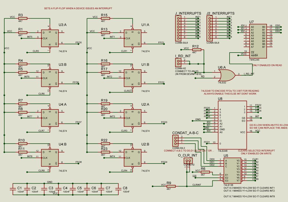
This Z80 interrupt module is being used to support interrupt handling on devices. For example i am using a 555 circuit to make a 20ms pulse that are fed into this module. The module signals an interrupt to the cpu via a Flip-Flop. When the cpu handles this interrupts, then it should clear this flip-flop by using an Out command.
The Module supports 8 devices. The jumper cable on RD_INT connects to Spare3 and that connects to the device select module so i can use an in command to communicate with this module. The jumper cable on CLR is connected to Extension 6 and that connects to the device select so i can use an out command to clear an interrupt. D0,D1,D2 are used to select 1-8 interrupts either to read or to clear. Other datapins can be used for reading other devices with the same port (Spare3). I am using D6 and D7 with the usb keyboard. Also you can use the same port for read and write, and different data pins to control the flip-flops.
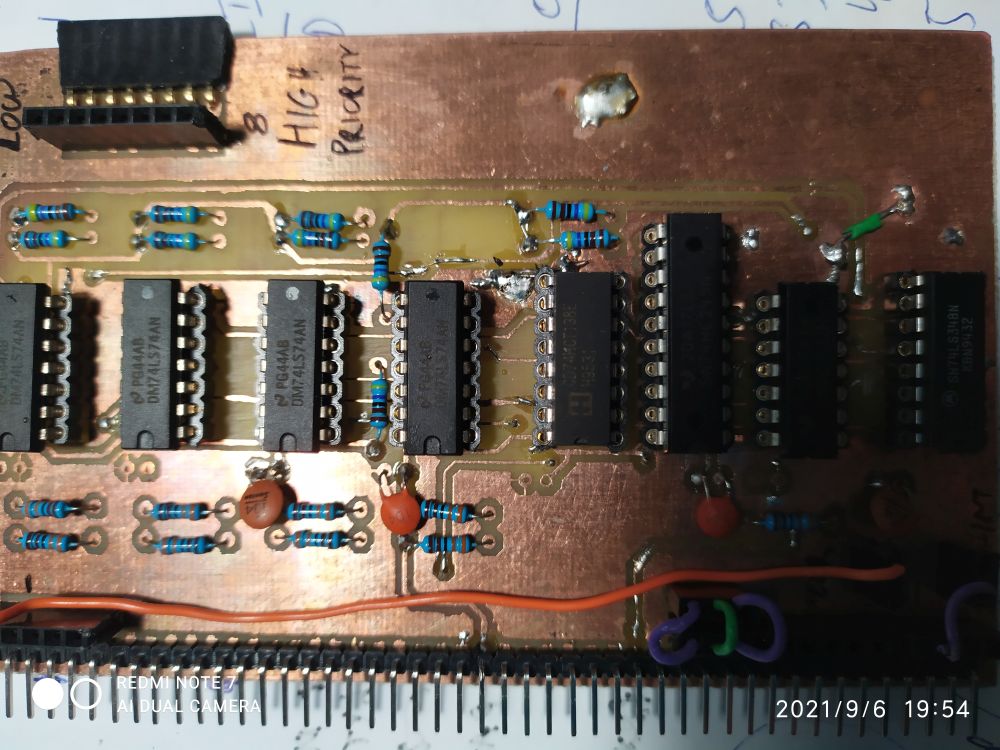
This PCB is double layered and it is difficult to be custom made, it’s better to use the Gerber files and order one on a factory. That said, all soldering, if you try to build one, are done on the bottom layer. As always first do the vias to connect the two layers.
Schematics
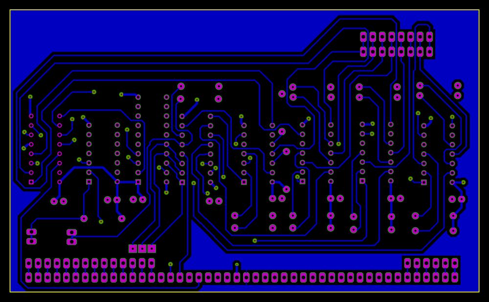
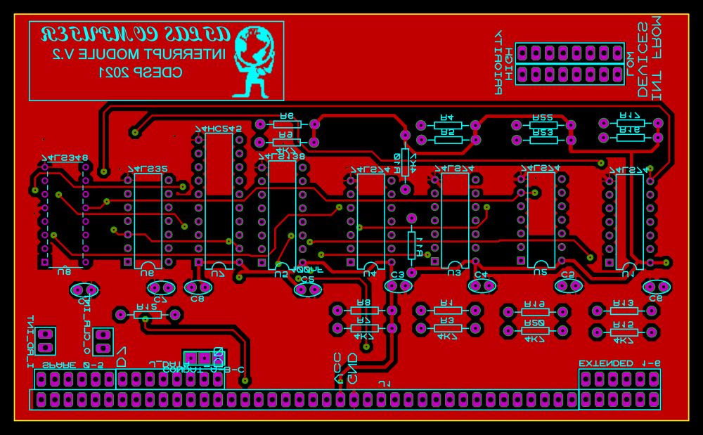
PCB