I am currently developing a single board computer(SBC) z80 Hardware Computer emulator and it is almost complete. Hopefully it would be possible to emulate any z80 home computer. I am currently working on the FPGA implementing several components and see if the hardware needs any alterations.
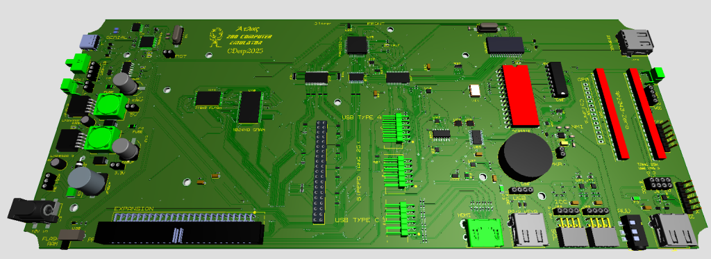
Specification
| Cpu | Z84C0020FEC |
| FPGA | Sipeed TANG 25K |
| Video | HDMI 800×600 with 64Kb dual port VRAM |
| Ram 1 | Flash RAM 512Kb |
| Ram 2 | Static RAM 1024Kb |
| Audio 1 | AY38912 |
| Audio 2 | SN76489 |
| Comms 1 | USB C RS232 |
| Comms 2 | I2C – 4 ports – 2 internal/external |
| Storage | USB-A |
| Keyboard | USB-A – PS/2 Mode |
| USB 1.1 Host | USB-A (can be connected to the FPGA USB Conn) |
| Expansion | 50 pin |
Power jack will need 12v 2A or more.
All logic will be implemented on the fpga.
CPU speed will be selectable 20,16,12,10,8,4,2 Mhz.
MMU can swap 8Kb pages to anyone of the eight z80 banks. Any Page can be set as read only from the Z80 so it is easy to simulate a rom.
Audio output (AY or SN) can be selected from the z80. There will be an internal speaker and a line out jack to connect to an amplifier.
Video will be permanent 800×600 with an HDMI connector. Every system will display its screen in that area, with pixel doubling when possible. So a system with 320×256 resolution will be displayed as 640×512 with borders around it to fill the 800×600 space. Also video is dual port so cpu speed will be at max.
Communication with other systems is done through the rs232 but with usb jacks so a simple data usb cable(type C) is needed to connect to to a pc (or a bluetooth module).
I2C interface can connect any i2c device. The i2c can be controlled either by the FPGA or the CPU and intend to have an LCD 16×2 controlled from the fpga along with a RTC to display the time on line 2, and messages on line 1.
For Storage a usb flash drive is all that is needed formated with fat32. The intention is to have the flash RAM boot and then load the system(Home Computer) from the usb, setting the memory map as needed. Of course it can be used as storage for the computer programs.
Keyboard will be handled by the fpga. The PS/2 keyboard code will be read from the FPGA, translate it and then passed to the computer.
The 50 pin expansion port will be used to program the flash ram. Flash ram will also be accessible from the cpu, but the bootable part will be read only. This can also be used to create other devices (2 signals available to the FPGA) as well.
I will try to have the cost bellow 200€ if possible. A 3d printed case is also on my plans as soon as i sent the board to be manufactured.
UPDATE:
Support for a Raspberry Pi Pico rp2040 for USB Mouse and Joystick support and also for a custom keyboard. This can be placed on the custom Keyboard or On the main PCB (to support only USB devices if you don’t have the custom Keyboard).
Bluetooth support for PC rs232 Comms selected (either type-c cable or Bluetooth). Needs a Bluetooth module.
Final Cost will be bellow 150€.
Gerber, BOM, and Pick and place:
Ok order set. 350€ for 5 boards with shipping and 90% assembled. I ll have to solder some components by hand. Extra components cost about 130€. The FPGA cost 195€. So total for 5 boards is 675€, that is 135€ for one board.
On the last version i included support for a Raspberry Pi Pico rp2040 for USB Mouse and Joystick support and also for a custom keyboard. This cost about 3€ from aliexpress and can be placed on the custom Keyboard or On the main PCB (to support a USB device).